|
Foster was finished machining the steel pivot bushings on the lathe, he had some time to build his quick sculpture 'Ricochet' from some leftover elements in the studio. His bullet shaped step series, was done on the metal lathe, which he has been learning about for the past few months. The inspiration of the 'Machinist' stemmed from teaching him to use the micrometer, and about processes and mindset of machining. 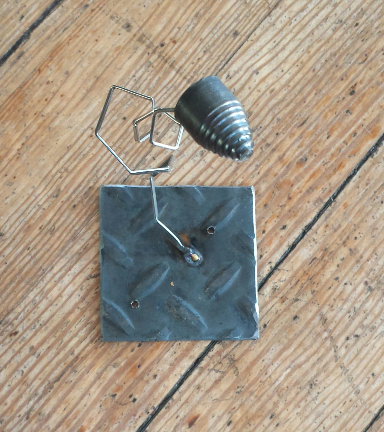 Foster found a piece of spring steel from a windshield wiper mechanism, he formed the coiling shape on the anvil and hammer. Base plate is remaining backing plate for the cub scout forming session we did with the entire troop when he was in second grade. 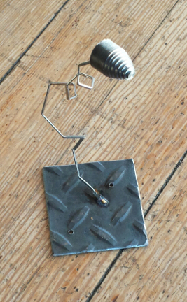 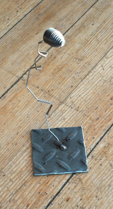
1 Comment
Foster has been interested in robotics (watch the video, the array of industrial robots are intriguing) as long as I can remember, he is ten now. The first idea we came up with while learning about the Arduino UNO, an open source microprocessor platform based on the ATmega processor made by ATMEL. The idea uses a variable resistor (Potentiometer) which is set up as a voltage divider. This is then converted via the Arduino acting as a analog to digital converter which then drives servo motors. We decided to build two models of the mechanism (robotic hand) one with Potentiometer, the other with servo motors at each articulating joint. As the model with Potentiometer is moved, the signals sent to the Arduino which converts the data then moves the second model with servos mirroring the first models movements. This is the first stage, in a quickly fabricated form using only two servo motors. eventually there will be five motors which articulate not only the gripping action, but also the wrist, elbow, and shoulder movements. This whole concept is similar to the Pantograph Engraving Machine that predate CNC (computer numerically controlled) machines. This design is based on the dimensions of Fosters hand, this way the model with the Potentiometers can be attached to his hand. As he moves his hand the motorized model will then move replicating the action of his hand remotely. This level of control is easy for a ten year old to work with, as it requires limited programming to achieve accurate control of two motors, and only a minimal programming to control five motors. 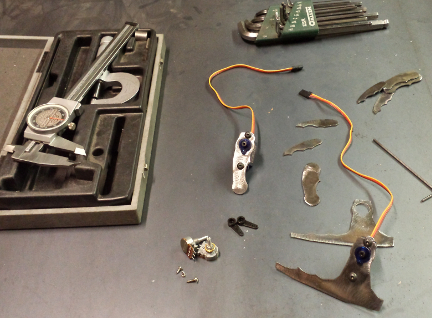 Pictured is the steel pieces of the two models based on Foster's hand, the servo motors (with the colored wires) and center bottom the potentiometers. 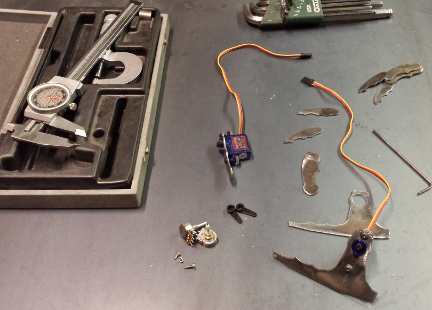 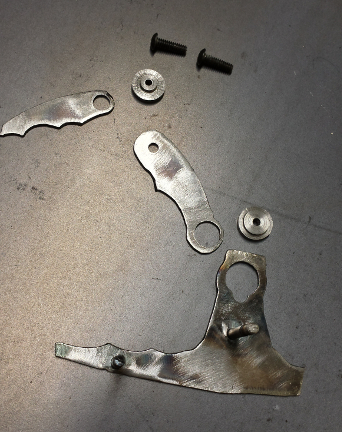 Pictured are the linkages, with the steel bushings Foster machined on the lathe. 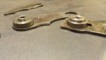 Close up of the linkages of the finger sections, with the steel bushings 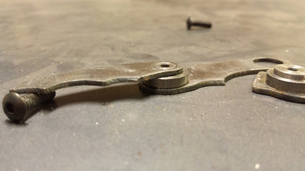 Partially assembled finger linkage, steel bushings 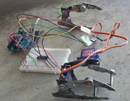 images of the entire assembly with the control hand, servo motor hand the Adruino UNO 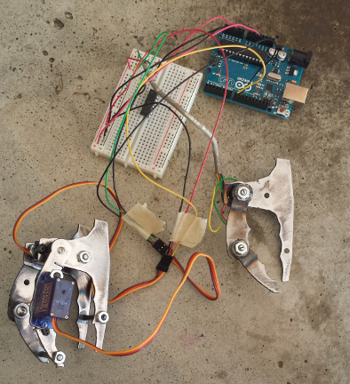 Robotic wrist: a starting place version 1.0Work on the rotating of the wrist: we decided to build a large surface bearing that would support the weight of the hand along with the weight of the object it would be grasping. The dimensions were based on the size of the servo to rotate the wrist, using an internal snap ring to secure the inner bearing in the shell of the outer bearing. This bearing is not the usual type used with ball bearings or roller pins, this is only rotating 90 Degrees so the friction is minimal, for the initial test design the two pieces are machined from steel, using lithium grease to reduce the friction. We opted out of using bronze bushing at this stage of design. The first two images are of the inside, internal snap ring and servo are visible. The two flanges pointing upward are attach to the inner ring of the bearing. The outer shell will attach to the hand assembly. The ends of the two flanges pointing upward will be used as part of a joint (to be developed later) to serve as the bending of the wrist. 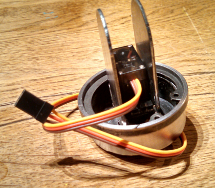 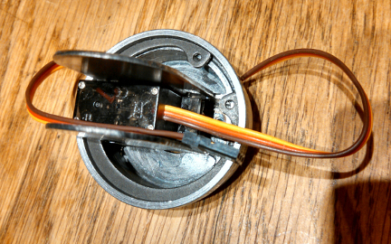 The next two images show the outer side of the wrist bearing, this outside of the shell will be the mounting point of the hand assembly discussed at the beginning of this post. 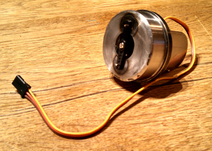 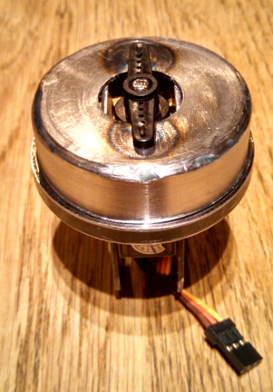 When building anything... design time is important, but eventually something has to be built. At the start of designing a new concept, we only have experience to base decisions on. There is no data related to the new concept to consider during the design process. After assembly, and testing, we have learned a few things; size limitations, sequence of fabrication, and most importantly the first version is lame. First, there is no room to mount a larger servo considering the inner diameter was designed around a specifically sized servo. Second, welding to machined components causes heat warping, this is a problem with precisely machined tolerances with mating parts of a bearing. All welding must be done prior to machining. This is common knowledge, but as we work on the next segments welding must be done after machining. After all the information we have learned from this first design, we feel it is best to move in another direction. Instead of remaking a similar version, we will start on version 2.0. The new version will resemble version 1.0 but the bearing design will be lighter and allow for different sizes of servos to be used. As sad as it is to have spent the time machining these components for them to serve only as a antiquated model, the new design may have never occurred without it. It is relatively easy to design something and feel confident it will work. The greatest thing you can learn is to then build that exact 'great design', and see how well it works, or how un-build-able it actually is. If Foster learns anything from developing his robotic arm... I hope it is the process of design in relation to building, and function. It is invaluable to be on both sides of the table. Obviously there will be more to follow, stay tuned. Robotic wrist: development and building version 2.0We have designed the new bearing mechanism which will support the hand and weight of the object it will be grasping. The use of three bearings, with a center race driven by a servo. This design allows for the option to use different sized servos, and is much lighter than the version 1.0. After the CAD work refining the design around the three rollers, the sheet metal has been cut out, the center hole was drilled and bored to diameter on the lathe, then here on the milling machine the hole is located with the use of a dial indicator. Next the hole pattern to mount the three rollers and mounting holes for the servo. I received an e-mail the other day about my blog and wanted to add more information about CAD. For further insight into CAD and its benefits, take a look here, Autodesk AutoCAD - Crash Course Hope some of you find this helpful. 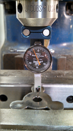 Finally the drill chuck is removed and a 4 flute end mill is installed via a Collet to machine the additional radius to fit the couture of the servo. 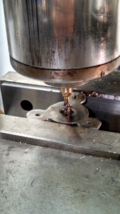 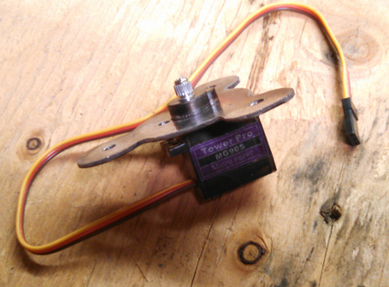 The bearing is assembled, with servo and also attached to the control circuit. The Potentiometer in the upper left corner will control the rotation angle of the bearing via the Arduino UNO microprocessor, as explained earlier in this post. 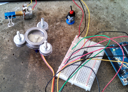 |
Daniel RomanoArtist/Designer/Sculptor Archives
September 2022
CategoriesCopyright © 2022
All Rights Reserved ROMANODANIEL |
 RSS Feed
