|
3 Comments
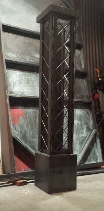
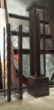
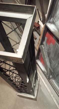
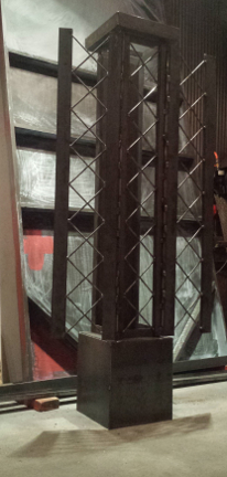
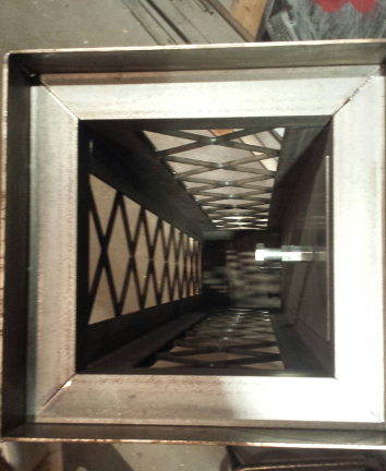
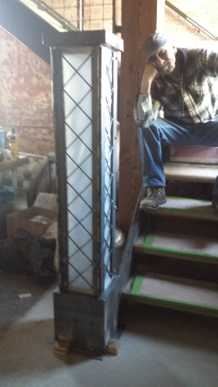
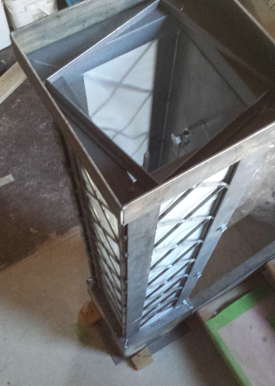
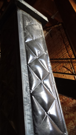
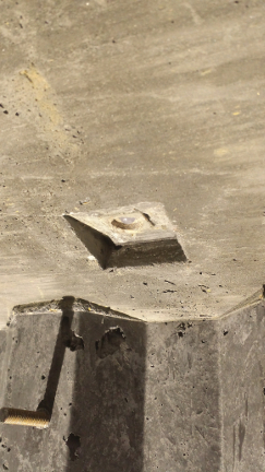
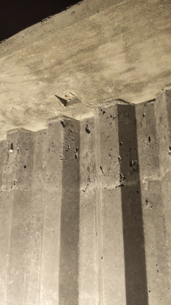
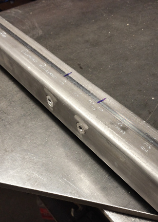
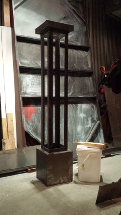 The Staircase incorporates 10" x 10" columns of rough-cut lumber, the stringers are 10" JR C-channel, so to stray from the use of steel and wood....also to tie in the MONOlithic concrete bar we decided to fabricate a steel from to place the concrete. Here is the base the form itself. Part of the form strays from the standard form style. Here is a simple fixture for aligning the components for the X's which will embellish three sides of the stair post. In the background the two silver bolts are visible, these are threaded unions to become cast in place 1/2-13 female threaded inserts to tie in the railing. 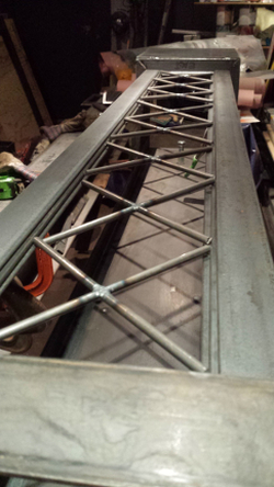 After both sides of the X's are welded they are trimmed as needed and added to the form. 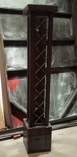 The first of three faces complete, there is much more to this form to follow, stay tuned. @ left is the stair post with the other two sides, @ right the hinged sides to aid in de-molding the form 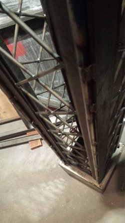 looking down the hinge tubes seen both sides of the form front. Looking down the inside of the form, bolt @ right acts as threaded insert to be embedded in concrete post Form complete and ready for concrete 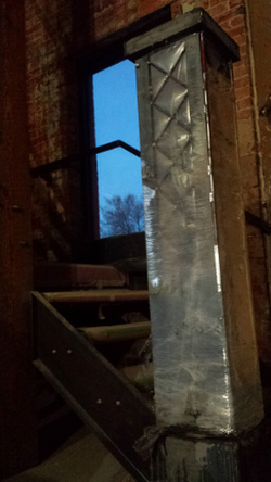 As the concrete was placed, stretch wrap (used to secure pallets) was added to hold the lower sections from expanding as the concrete head pressure increased. Concrete weighs approx 150# per cubic foot. In this case the from height is 5 ft: the pressure at the bottom of the form is 750 pounds per square foot. So 12 inches up the pressure on the diamond would be approximately 600 pounds per cubic foot. Dividing this by 144 to find pressure per cubic inch (600/144) 4.166 pounds. (the diamond is 3.75 x 3.75). The pressure at the bottom diamond approx (4.166 x 16) 66.65 pounds. The pressure at the top diamond is approx 16 pounds. The outer form has been removed in this image, the steel frame work of the inner form was later cut off in pieces.
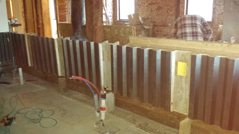
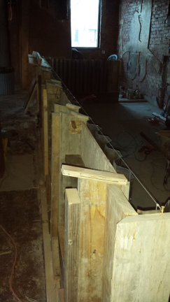
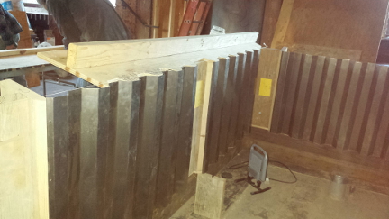
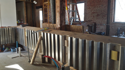
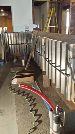
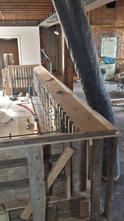
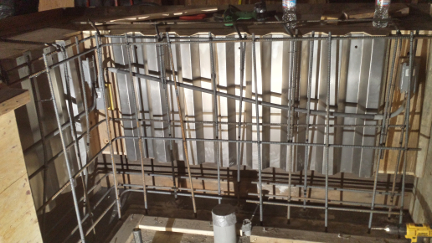
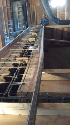
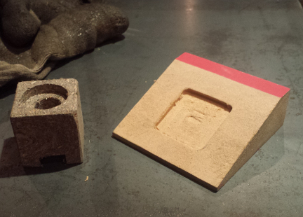
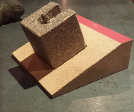
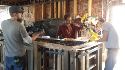
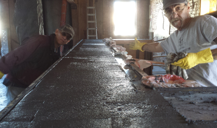
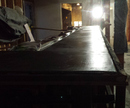
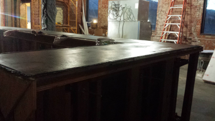
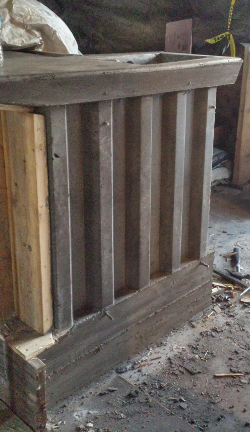
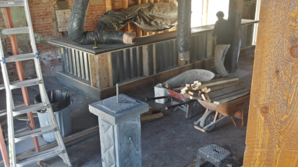
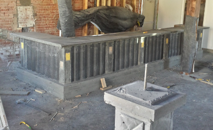
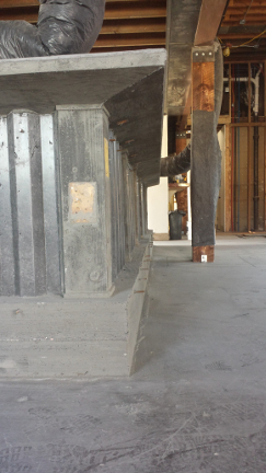
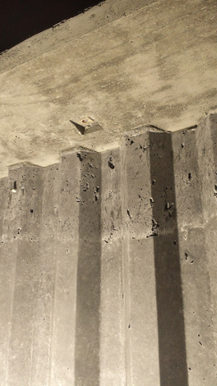
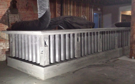
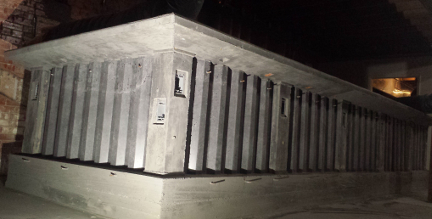
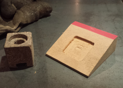
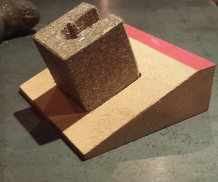
Main Floor bar of the N3 Taphouse incorporating western rib metal roofing, along with my favorite ....board forming. The design of the out side form, having a step at the bottom, was super unstable to start with. Alignment of the front from line layout of the sloping underbelly of the bar top, scribing and cutting to mate with the formed steel. 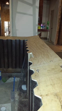 Turning the corner of the underside of the bar top, this surface is where the 10mm RGB LED sockets will mount from the previous blog: up-cycled Trex... Adding Block outs for the outlets on the patrons side of the bar. Installation of the electrical conduit, patrons side First row of rebar tied in place completion of the first row of rebar 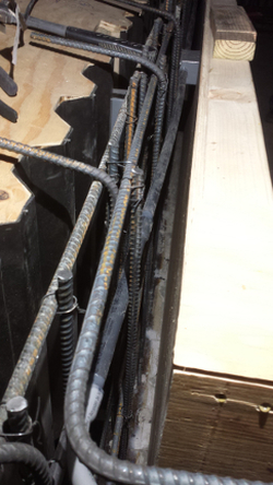 Second row of rebar, inside form Tenders side.... with the rebar turning towards the patrons side Stead fast assistant on the N3 Project M$M mark tie-ing the 6X6 mesh along the top of rebar 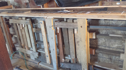 The combination of the formed steel sections, and board formed columns, the front face of the form couldn't use conventional whalers. A chance to use the small pieces of lumber we have been saving for the entire job just for this purpose. Also as opposed to conventional form ties, the varying width of the form we opted to use 3/8" all-thread This wedge shaped block was made as opposed to machining an angle on the Trex block. (bad planning on my part). The under-side of the bar top has a 12 degree angle. In order to have the light emitting towards the lower face of the bar the angle on the block has to be 12 deg (to make the light point straight down) + 10 more degrees to direct the light on the face. the 22 degree face has a pocket to locate and keep the Trex block from moving as the concrete is placed in the form. The Block will mount in the milled pocket in the wedge block. Note: the hole where the LED will mount is pointing down. as the lower bar surface is the steel surface in this image.
Vibrating the concrete as it is placed is most important to remove air pockets, and infill the details of the forms Sreed the concrete with a ROD to start the process of producing as flat a surface as possible
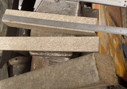
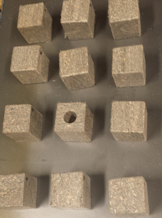
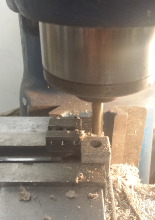
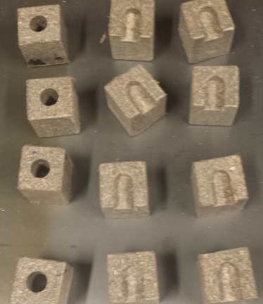
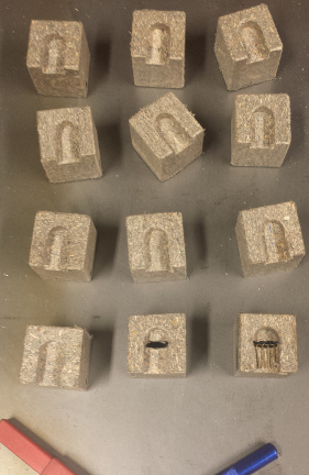
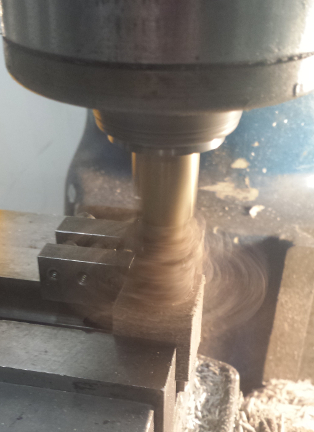
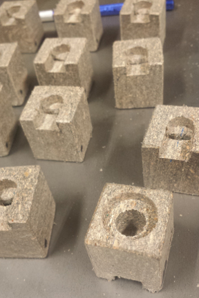
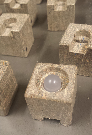
I have been machining non conductive parts from Trex for years. It is fairly solid, and fine for parts where rigid forms are not important. Plus these remind me of Tofu chunks. 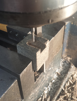 milling the .125" slot (with an endmill) through the center connecting the bottom slot with the bored hole from he top bottom right block the pins are visible from the bottom. these will lead the the control circuit and Arduino clone.
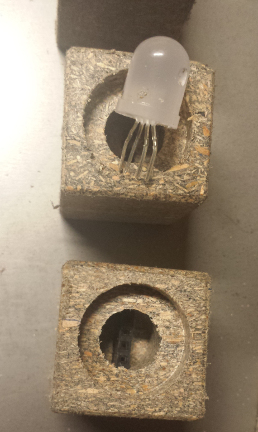
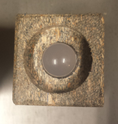
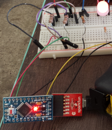
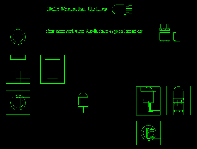
10mm RGB LED, and the socket visible within the bored hole lower Ardunio clone used to control the RGB LED (12 of which will accent the concrete bar) test circuit show CAD file for the LED socket more to follow..... see the concrete bar post...
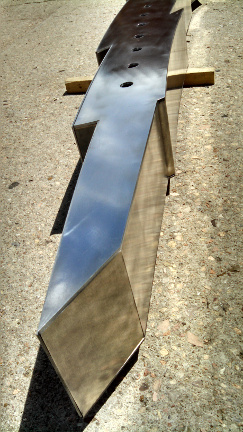
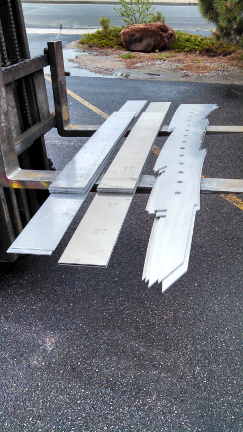
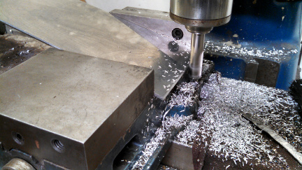
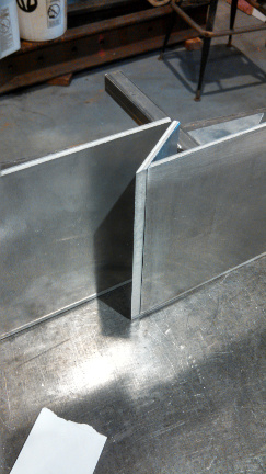
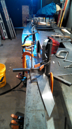
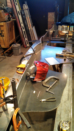
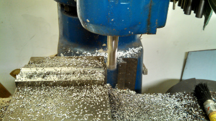
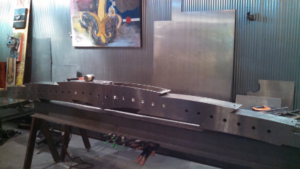
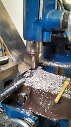
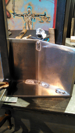
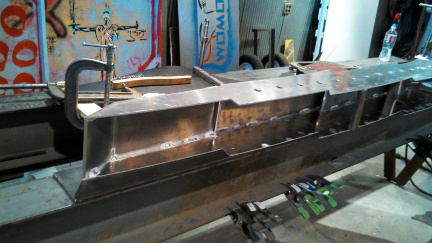
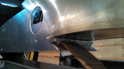
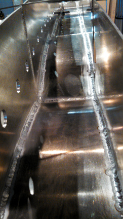
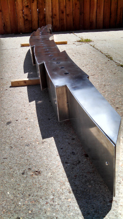
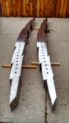
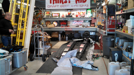
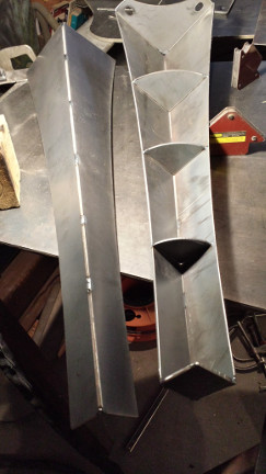
Work started on the two lightning bolt tap manifolds with 30 taps each, for: N3 Tap House. Design work on the project started from a sketch made the day of the phone call from Buck from Thirst aid in Denver CO. I had three weeks to design and build two 30 tap manifolds, now the clock has started, something like 18 days. Thirst Aid is so busy, if I didn't deliver the manifolds by the 16th of May then the install would be pushed from early June to late September. Picking up the 5052 Aluminium freshly water jet. As you can see they didn't consider protecting the material with cardboard or a pallet, just drag it across the forks. needless to say the material was found to have scratches and this is something you have to work with if you are forced to use new suppliers. The 6" sheared pieces of 3/16 material had to be machined to the correct angle prior to welding. The two mating pieces will be welded from the inside, the inside edges above in the lower image will be welded in the inside also, these require no mitered edges. The long process of forming the 3/16 elements to match the face plate of the manifold, then the aligning and clamping prior to TIG welding the Aluminium. Milling the top spreaders of the manifold as a group prior to mitering, fit, and welding. The first of the two manifolds in the process of fitting and forming the top covers. Milling the angle for a piece of the second manifold. Tack welding of the elements, then the process of TIG welding the entire inside of the enclosure. Backing up the outside of the weld to seal seam to be TIG welded. This eliminates contaminates to enter the weld area protected by Argon Gas. View of the inside, and the continuous welds down both sides of the 13 and 1/2 foot manifold. First manifold lightly polished with only #3 rouge. Side view of the soft polish of the surface. two 13+ foot 30 tap manifolds ready to pack up. Delivery to: Thirst Aid for the install of the tap faucets, and coolant lines. Infamous Buck pictured at left.
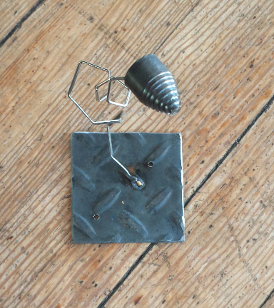
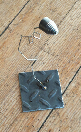
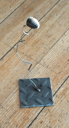
Foster was finished machining the steel pivot bushings on the lathe, he had some time to build his quick sculpture 'Ricochet' from some leftover elements in the studio. His bullet shaped step series, was done on the metal lathe, which he has been learning about for the past few months. The inspiration of the 'Machinist' stemmed from teaching him to use the micrometer, and about processes and mindset of machining.
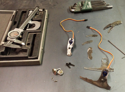
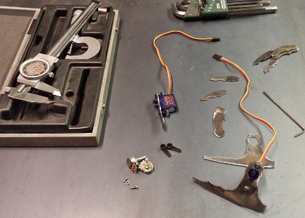
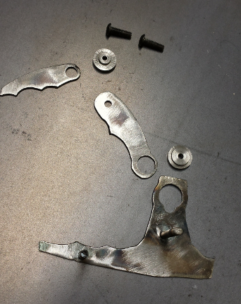
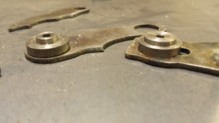
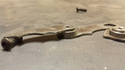
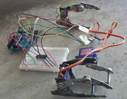
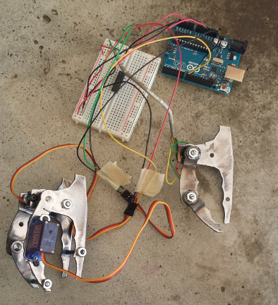
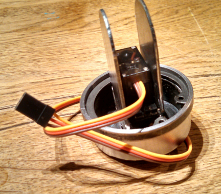
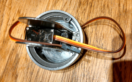
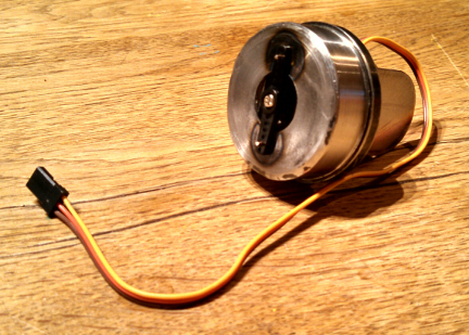
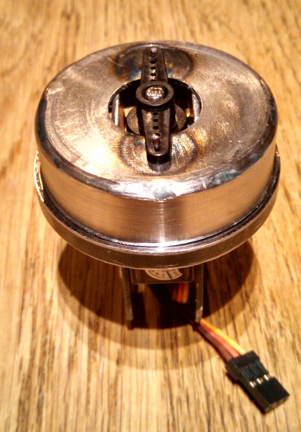
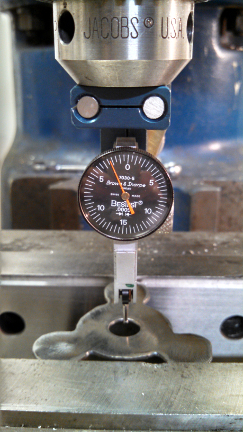
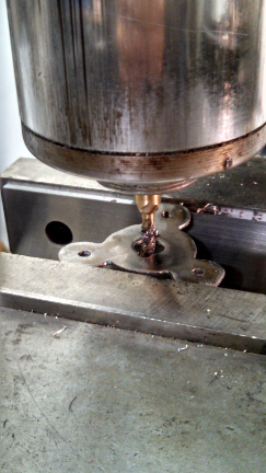
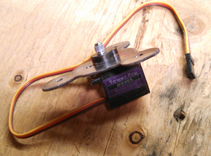
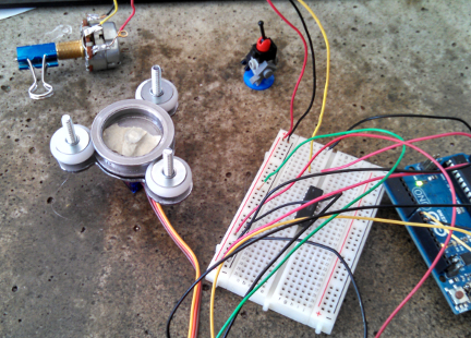
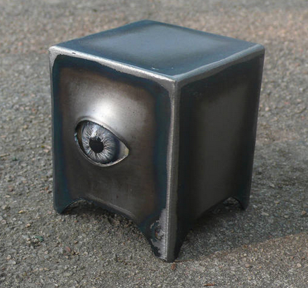
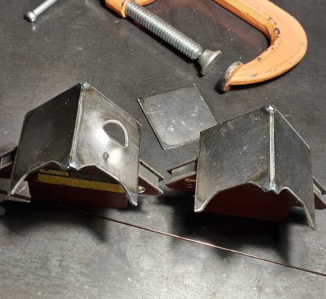
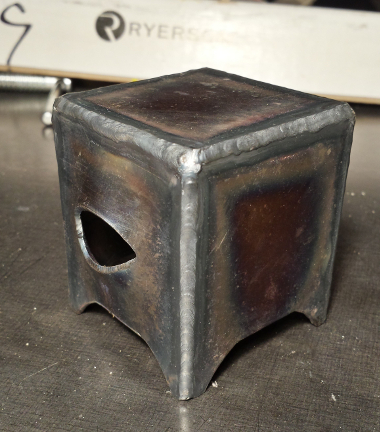
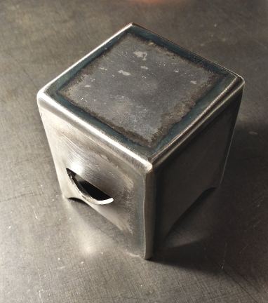
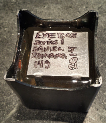
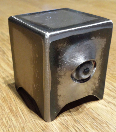
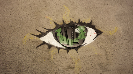
Foster has been interested in robotics (watch the video, the array of industrial robots are intriguing) as long as I can remember, he is ten now. The first idea we came up with while learning about the Arduino UNO, an open source microprocessor platform based on the ATmega processor made by ATMEL. The idea uses a variable resistor (Potentiometer) which is set up as a voltage divider. This is then converted via the Arduino acting as a analog to digital converter which then drives servo motors. We decided to build two models of the mechanism (robotic hand) one with Potentiometer, the other with servo motors at each articulating joint. As the model with Potentiometer is moved, the signals sent to the Arduino which converts the data then moves the second model with servos mirroring the first models movements. This is the first stage, in a quickly fabricated form using only two servo motors. eventually there will be five motors which articulate not only the gripping action, but also the wrist, elbow, and shoulder movements. This whole concept is similar to the Pantograph Engraving Machine that predate CNC (computer numerically controlled) machines. This design is based on the dimensions of Fosters hand, this way the model with the Potentiometers can be attached to his hand. As he moves his hand the motorized model will then move replicating the action of his hand remotely. This level of control is easy for a ten year old to work with, as it requires limited programming to achieve accurate control of two motors, and only a minimal programming to control five motors. Pictured is the steel pieces of the two models based on Foster's hand, the servo motors (with the colored wires) and center bottom the potentiometers. Pictured are the linkages, with the steel bushings Foster machined on the lathe. Close up of the linkages of the finger sections, with the steel bushings Partially assembled finger linkage, steel bushings images of the entire assembly with the control hand, servo motor hand the Adruino UNO Robotic wrist: a starting place version 1.0Work on the rotating of the wrist: we decided to build a large surface bearing that would support the weight of the hand along with the weight of the object it would be grasping. The dimensions were based on the size of the servo to rotate the wrist, using an internal snap ring to secure the inner bearing in the shell of the outer bearing. This bearing is not the usual type used with ball bearings or roller pins, this is only rotating 90 Degrees so the friction is minimal, for the initial test design the two pieces are machined from steel, using lithium grease to reduce the friction. We opted out of using bronze bushing at this stage of design. The first two images are of the inside, internal snap ring and servo are visible. The two flanges pointing upward are attach to the inner ring of the bearing. The outer shell will attach to the hand assembly. The ends of the two flanges pointing upward will be used as part of a joint (to be developed later) to serve as the bending of the wrist. The next two images show the outer side of the wrist bearing, this outside of the shell will be the mounting point of the hand assembly discussed at the beginning of this post. When building anything... design time is important, but eventually something has to be built. At the start of designing a new concept, we only have experience to base decisions on. There is no data related to the new concept to consider during the design process. After assembly, and testing, we have learned a few things; size limitations, sequence of fabrication, and most importantly the first version is lame. First, there is no room to mount a larger servo considering the inner diameter was designed around a specifically sized servo. Second, welding to machined components causes heat warping, this is a problem with precisely machined tolerances with mating parts of a bearing. All welding must be done prior to machining. This is common knowledge, but as we work on the next segments welding must be done after machining. After all the information we have learned from this first design, we feel it is best to move in another direction. Instead of remaking a similar version, we will start on version 2.0. The new version will resemble version 1.0 but the bearing design will be lighter and allow for different sizes of servos to be used. As sad as it is to have spent the time machining these components for them to serve only as a antiquated model, the new design may have never occurred without it. It is relatively easy to design something and feel confident it will work. The greatest thing you can learn is to then build that exact 'great design', and see how well it works, or how un-build-able it actually is. If Foster learns anything from developing his robotic arm... I hope it is the process of design in relation to building, and function. It is invaluable to be on both sides of the table. Obviously there will be more to follow, stay tuned. Robotic wrist: development and building version 2.0We have designed the new bearing mechanism which will support the hand and weight of the object it will be grasping. The use of three bearings, with a center race driven by a servo. This design allows for the option to use different sized servos, and is much lighter than the version 1.0. After the CAD work refining the design around the three rollers, the sheet metal has been cut out, the center hole was drilled and bored to diameter on the lathe, then here on the milling machine the hole is located with the use of a dial indicator. Next the hole pattern to mount the three rollers and mounting holes for the servo. I received an e-mail the other day about my blog and wanted to add more information about CAD. For further insight into CAD and its benefits, take a look here, Autodesk AutoCAD - Crash Course Hope some of you find this helpful. Finally the drill chuck is removed and a 4 flute end mill is installed via a Collet to machine the additional radius to fit the couture of the servo. The bearing is assembled, with servo and also attached to the control circuit. The Potentiometer in the upper left corner will control the rotation angle of the bearing via the Arduino UNO microprocessor, as explained earlier in this post. The EYEBOX series is now in its 4th series which doesn't include the flowering EYEBOX variations. The origin of this series was initiated from the Eye of Providence found on the reverse side of the ONE DOLLAR Federal Reserve Note. The first iteration was the EYE of Providence. The next version started the EYEBOX series with the first of which was based on the console television. As stated in my BIO, my parents started a television and radio business in 1951. The television from at times... has been something I relate to things in my life. Just the other day a collector purchased one of the series 1 EYEBOX from one of Charles Saatchi's sites, www.saatchiart.com. The original versions were H 2.5" W 2" D 2" this version I decided to make larger and of a thicker gauge material. After cutting and forming the pieces, tack welding, TIG welding, then grinding and sanding. The earlier versions included a welded plate on the bottom, this version has the cavity filled with epoxy resin w/embedded aluminium plate.
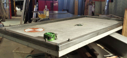
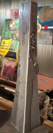
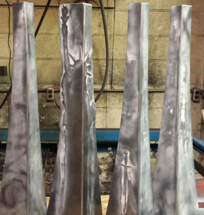
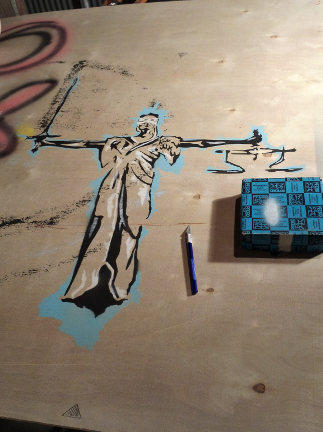
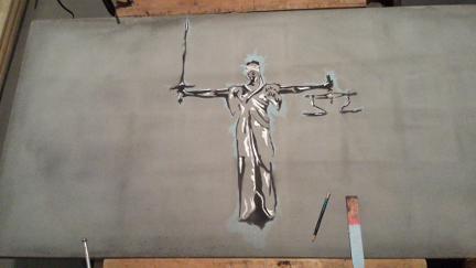
Recent work on a concrete topped desk, with steel framework. The request included freedom of design, other than the dimensions of H 36" W 60" D 30".... these parameters are easy to stay within. The top of frame was cut and prepared for the threaded inserts, and mounting studs. The legs are to be removable for shipping, which requires more thought as opposed to welding the legs directly to the upper frame. Below the multiple sets of threaded inserts are TIG welded in to the side of the top frame, this keeps the top surface free. The selection of hi-resolution video displays can float above the desk surface. IZ medallion in bedded in the bottom surface of the concrete complete with graphics, Also a Fleur-de Lis was also embedded in the bottom surface with related graphics. Early stages of the top frame with the de-molded desk top. Assembly, tack welded leg sections. The outer facing corner of the Desk is the most prominent element as one approaches the area, the leg on this corner is different from the other three, for variation, the use of the number three, and to incorporate steel overlay of an Statue of Liberty. The Leg sections are 6" x 6" at the top and usually 2" x 2" at the foot, though this leg was adapted to accommodate the overlay. highlighting work on the legs prior to clear coat. The work on producing the image of 'lustitia' in three colors, here a sample done on plywood. finally on the concrete top, prior to sealing and wax. Here I decided to have a lightly colored pigment as opposed to the color work on the bottom of the desk top. This is just a suggestion of and image not a vivid image from a magazine.
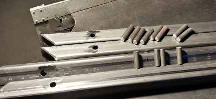
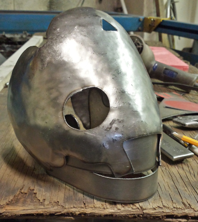
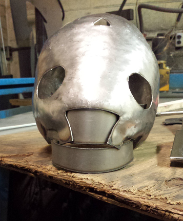
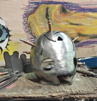
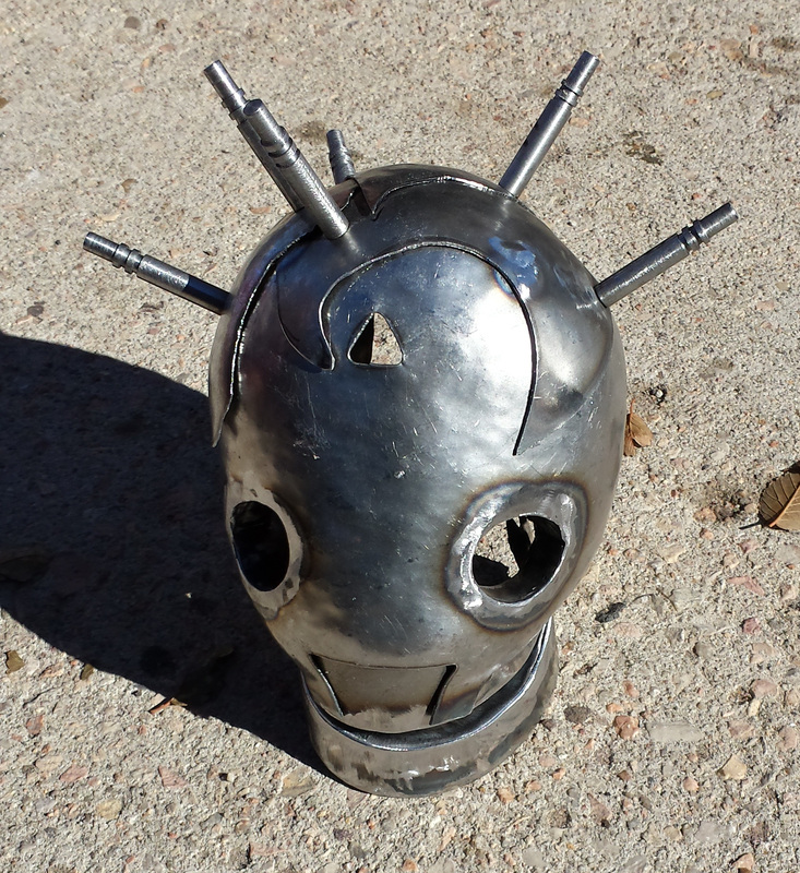
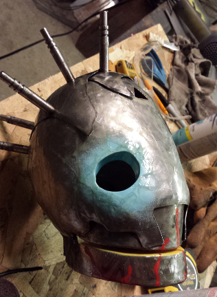
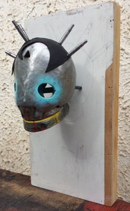
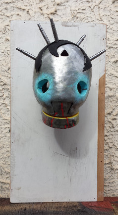
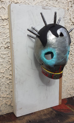
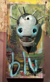
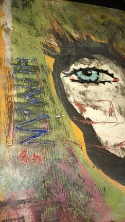
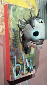
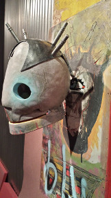
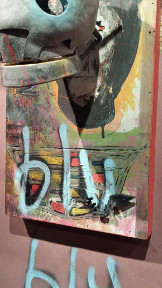
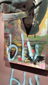
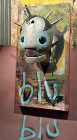
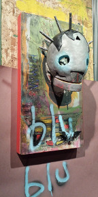
New work on an old design Jeremiah Houck and I collaborated together for some work exhibited at the "Carbon & Clay: Conflicting Connections" show in 2008. Originally I had two copies cut, and one piece was finished for the show, the other remained stored in the Studio until last week. Work started with forming and welding, organizing some ideas around this new version of the original work. The one piece skull was designed with no top, here it is taking shape with basic forming, the lower jaw has been placed in location below the upper teeth section. I decided to design the overlapping steel for the top of the head, to resemble the hairstyles of the 1920's. The copper colored pins are Clecos (temporary fasteners) which are used in sheet metal fabrication to hold sections to be riveted together as all the remaining holes are made or additional pieces are added to the correct location. These are spring loaded pins which pull the lower piece of metal together, in this case through a .125" hole. As the pieces are riveted together a Cleco is removed and rivet installed, then the next Cleco is taken out etc. I was planning on using solid steel rivets to connect the layers, though after having the Clecos in for part of a day I decided to machine Cleco like pins to replace the solid steel rivets. I then TIG welded the bottom of the pins in place instead of making deform-able rivet ends. AS pictured above the lower jaw has been fabricated wrong, cutting the welded edges top and bottom to be reshaped then re-welded. After, reworking the lower jaw to have a straight line and follow the upper curve, then welded the jaw to the upper skull. Prior to Sealing the layers of 20 gauge steel sheet metal, and painting, additional 3/8" steel bar stock has been machined and added to mount the head to a future panel. After work on the panel, and other refinements to the head. Gallery select images below |
Daniel RomanoArtist/Designer/Sculptor Archives
September 2022
CategoriesCopyright © 2022
All Rights Reserved ROMANODANIEL |


 RSS Feed
